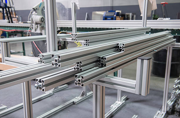

Before a frame reaches the shop floor, its loads and support conditions should already be understood. These calculations show whether the selected profiles will stay stiff, whether the joints can transfer force, and whether the base will remain stable during use. Careful planning also prevents an aluminum framing kit from becoming heavier or more complicated than the application actually requires.
Start by Mapping Every Load the Frame Will Carry
Initial calculations should begin with the full working weight, not just the main machine or fixture. Shelves, panels, motors, controls, tools, stored parts, cable trays, and accessories all add force to the structure. Concentrated loads deserve special attention because a motor or cabinet mounted at one point can stress a beam differently from weight spread evenly across its length. Future additions should also be included when they are reasonably expected. Accurate load mapping gives the selected aluminum framing material a realistic design target rather than an optimistic number based on an empty frame.
How Far Can a Profile Span Before Deflection Becomes a Problem?
Span length strongly affects bending. Even a T slot extrusion that feels rigid over a short distance can sag noticeably once supports move farther apart, even though the actual load has not changed. Designers use profile section properties, material stiffness, support conditions, and load placement to estimate deflection before installation. Acceptable movement depends on the job, since a basic guard may tolerate more flex than a sensor mount, conveyor rail, or inspection fixture.
Adding a center support can sometimes solve the problem more efficiently than moving to a much heavier profile. Shorter spans reduce bending quickly and may let the frame keep a slimmer footprint. Available MiniTec extruded aluminum framing comes in different sections, allowing engineers to compare stiffness and weight instead of automatically choosing the largest rail available.
Profile Orientation Changes the Bending Calculation
Rectangular profiles do not resist force equally in every direction. Turning an extruded aluminum T slot member so its deeper dimension faces the load can increase bending resistance without changing the amount of material in the frame. Section-property tables normally provide values for both principal axes, and the correct value must match the installed orientation. Ignoring that detail can make a calculation look safer than the finished structure really is. Correct orientation becomes especially useful where space limits profile size but the frame still needs good vertical stiffness.
Connections Need Their Own Strength Check
Bolted joints transfer force from one profile to another, so profile capacity alone does not define the strength of MiniTec Aluminum Framing. Brackets, Power-Lock fasteners, joining plates, T-nuts, and bolts each have limits that should fit the expected load path. Joint rotation also matters because a connection that slips slightly can make a tall frame feel flexible even when the rails remain straight.
Fastener placement can change how well a joint handles bending or twisting. Multiple attachment points usually spread force more effectively than one heavily loaded bolt, while wider plates can improve stiffness around demanding corners. Controlled tightening keeps the connection secure without crushing a slot edge or damaging threads in the T slot aluminium extrusion.
Dynamic Forces Can Be Higher Than Static Weight Suggests
Moving equipment creates loads that do not appear on a simple weight list. Conveyors, actuators, robotic devices, drawers, and rotating machinery introduce acceleration, vibration, stopping forces, and repeated cycling. Dynamic analysis may apply appropriate allowances or examine the motion directly so the frame is not sized only for equipment sitting still. Fatigue also deserves attention where loads repeat throughout every shift. Bracing, stronger joints, or different support spacing may be needed even when the static calculation appears comfortable.
Will the Base Resist Sliding, Rocking, and Tipping?
Stability calculations look at the whole structure rather than a single beam. Tall frames, wide doors, side-mounted equipment, and cantilevered arms can shift the center of gravity and create overturning moments at the floor. Base width, leveling feet, anchors, and equipment placement should keep those forces inside a safe support area.
Floor anchors need enough capacity to resist the tension and shear passed through the mounting plates. Concrete condition, anchor spacing, embedment, and distance from slab edges can affect the result. Mobile frames require a different check because caster position, wheel rating, and braking forces become part of the stability calculation.
Build a Safety Margin Into the Final Design
Calculated capacity should not equal the exact expected operating load. An appropriate factor of safety gives the structure room for reasonable uncertainty, minor overloads, material variation, and changes that occur after installation. The required margin depends on the application, loading type, environment, and consequences of failure rather than one universal number. Final review should compare stress, deflection, connection capacity, stability, and operating conditions as one system. Through MiniTec Solutions, manufacturers can access MiniTec Aluminum Framing profiles, connection hardware, and modular components that can be selected around calculated span, load, movement, and support requirements, helping manufacturers build frames that suit the actual job instead of relying on rough size estimates.